| Added | Thu, 24/08/2017 |
| Sources | |
| Феномены | |
| Version type |
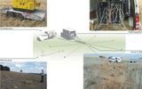
Geological dictionary defines the seismic profile as a straight line, rarely broken line on the Earth's surface along which the seismic receivers are arranged for the study of elastic (seismic) waves.
Distinguish between longitudinal profiles where the seismic receivers and the shot points are located on one straight line, and not longitudinal, where the seismic sensors are in a line not passing through the point of explosion.
On the arc profile, the shotpoint is located in the center of the circle, arc with seismic sensors.
Observing system (arrangement of shot points and seismometers) to ensure the continuation of the study of seismic boundaries, are referred to as systems of continuous profiling, the profiles — continuous.
The system of observations on the profile are selected so that at the lowest cost to trace and identify the kinematic and dynamic characteristics of the useful of the waves, the study of which is necessary for the solution of geological and methodological problems.
Length of anchorage of seismic receivers (section of the profile where the seismic receivers) depends on the number of channels of seismic stations and the distance between the seismic sensors.
The latter are chosen so that the signals coming sequentially to the seismic sensors, confidently traced from channel to channel.
For the method of reflected waves (MOB) is 20-30 m, rarely (in hard sassover. conditions) of 10-15 m.
In the correlation method of refracted waves (cmrw) distance between receivers is equal to 40-100 m.
Location that depends from tasks, geological structure, seismic and geological and topographical conditions of the project area.
The main profile is sent across the stretch of structures and tectonic lines; separate binder along the line of stretch.
Search and detailed studies are characterized by a density and the method of network location profiles on the ground and observing systems. Mainly seismic observations are made on the longitudinal profiles.
Not longitudinal profiles are used to study steeply dipping layers, and tracing violations. They determine the relative limits are exceeded along the profile. Therefore, they are used in combination with longitudinal profiles. Not longitudinal profile should be located at a distance from the point of explosion, which would be possible follow-up phases of the useful waves. Distance is determined empirically. Length not longitudinal profile depends on the angle of inclination of the studied borders and distances between the profile and the point of explosion.
In still bedding layers and the presence of marker horizons is the so-called dotted profile, where the exploration lines have a number of separate samosogrevanie; this technique works is less informative, but cheaper.
There are 2D and 3D seismic surveys.
The result of 3D seismic surveys receive a model of a layered medium with a complete lack of symmetry, the most feasible when the depth and configuration of the layers behave arbitrarily in any of the 3 directions. If 3D is not carried out of the profile and areal observations. The main advantage of 3D seismic lies in the fact that the information coming to the surface at different azimuths and angles is recorded and processed together, giving the opportunity to restore the spatial position of the reflecting boundaries and to obtain three-dimensional picture of the object. No 2D seismic surveys cannot replace the 3D, however often are not located separate seismic profiles. Industrial use of 3D began in the mid-80s.
Translated by «Yandex.Translator»
Related facts
Log in or register to post comments


